GREEN MOBILITY
Concept design using vehicle system simulation : BEV / FCEV / Hybrid ICE
Work flow of development
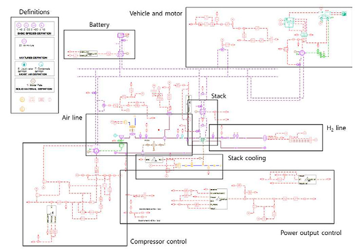
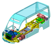
1. Packaging Design
- FC/PE system
- FC/PE Cooling system
- H2 supply system
- Wire harness
- HVCU
- Energy flow display
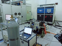
2. System Evaluation
-
FC system
- Performance
- Efficiency - HVCU control unit inspection test
- Battery/PE system
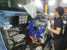
3. Proto vehicle development
- Repainting
- Disassembly
- Components installation
- Filling hydrogen
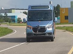
4. Proto vehicle test
-
Calibration
- Driving control
- Power control -
Test
- Fuel economy test
- Drivability test
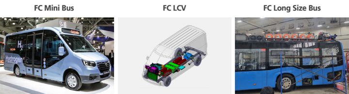
FCEV develop.
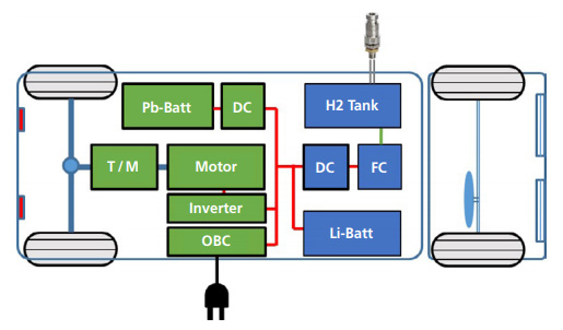
Tenergy solution :COC (Constant Output Control) fuel cell hybrid system
High vehicle system efficiency,
Low FC degradation.
| Hyundai [Nexo] | TOYOTA [SORA] | TENERGY (COC FC system) | Remark | |
| Motor | 120kW | 226kW | 100kW | - |
| Battery | 1.6kWh | 7.5kWh | 24kWh | QC, OBC charge |
| FC system | 95kW | 228kW | 30kW | High effi. const. output |
| H2 tank | 157L | 600L | 153L (6.0kg) | 700bar, Type 4 |
| HEV type | Full FC type | COC type | - | |
| Pros. | Low weight | High effi., FC low degradation | - | |
| Cons. | Low effi., FC degradation | High weight | - |
HEV develop.
Tenergy solution :Series and parallel multi mode system.
▶ Simple structure, High performance
Parallel
| Architecture | OEM | ||
| P0 / P1 | 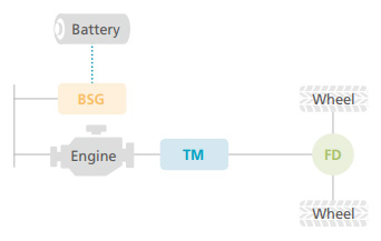 |
 |
|
| P2 | 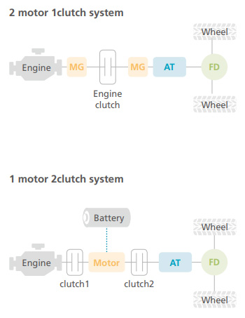 |
 |
|
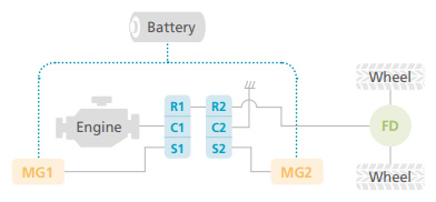
Multi Mode
| Architecture | OEM | ||
| Power-split / Parallel / Series | 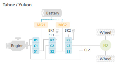 |
 |
|
| Series+ Parallel | 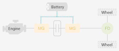 |
 |
|
Power-split
| Architecture | OEM | |
 |
 |
|
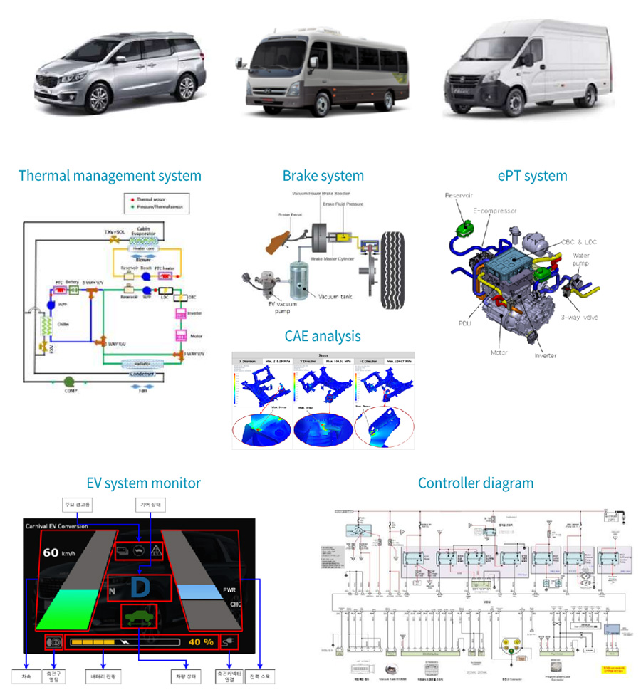
EV develop.
Tenergy solution :EV Conversion from ICE vehicle
Development of EV systems (TMS, ePT, Monitor, Controller, etc.)
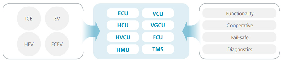
Controller develop.
Expertise in custom crafting powertrain controllers for diverse vehicle types
- Specialized feature implementation for Conventional Vehicle, EV, HEV and FCEV
- Cooperative control with ECUs
- Considering fail-safe operation
- Employing diagnostic strategies
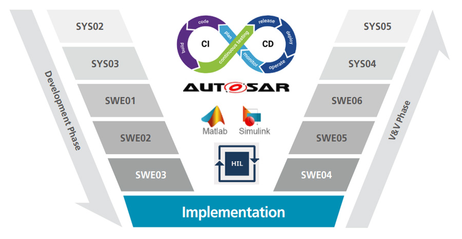
Automotive V-Model Process to design systematic development of software & system
- Adopting AUTOSAR to enhance standardization, compatibility and reliability
- Implementing Continuous Integration and Continuous Deployment (CI / CD)
- Leveraging Model-Based Design (MBD) for improved system design and testing
- Integrating Hardware-In-the-Loop Simulation for real-time testing and validation
Overview
1. Literature Survey
- Patent
- Maintenance manual
- BM video
- Public articles

2. Data Acquisition and Test Design
- CAN reverse engineering
- Installing sensor
- Design test schedule

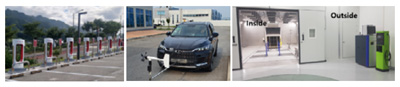
3. Vehicle Test
- Coast down test
- Chassis-dyno test
- Real driving test
4. Vehicle Control Strategy Analysis
- Analysis system
- Analysis test results
- Analysis control strategy
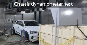
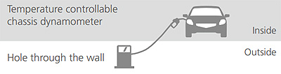
Vehicle test
Chassis dynamometer test
- Simulate real road driving
Driving, slope climbing & charging - Operating range: -20℃ ~ 55℃
Charging
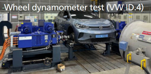
Wheel dynamometer test
-
Direct measurement of PT output
Performance
Efficiency
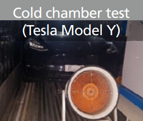
Cold chamber test
-
Operation range: -30℃ ~ 0℃
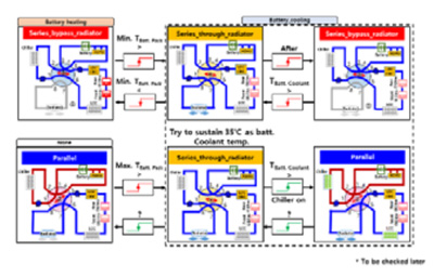
Thermal management
Battery charging
EV Charger(~100kW)